Series 67 Direct Mode DIP Switch Settings
The below instructions help describe how to set the DIP Switches on a Series 67 Intrinsically Safe relay in Direct mode. This will help users ensure the relay is working properly and help explain the operation and wiring of the board.
The relay works off liquids natural conductive properties and is typically wired to conductivity probes. However, all Warrick conductivity relays also work with dry contact switches, like a LS-800 float level switch, or a Series M Mechanical Tilt Float switch, or any non-voltage storing device. The Series 67 is intrinsically safe, which means it limits the voltage and current traveling to the sensor to a level that is incapable of producing a spark that may ignite flammable gases. Jumpers may be placed between the sensor contacts to help test the board and simulate a switch closure or conductance between two probes.
Setting the DIP Switches
The Series 67 relay has DIP Switches that control the logic of the relay. They can be set in either Direct Mode or Inverse Mode, for each of the 4 channels. There are also two DIP Switches for the remote load contacts near the power supply. The below shows where the DIP switches are located on the board.
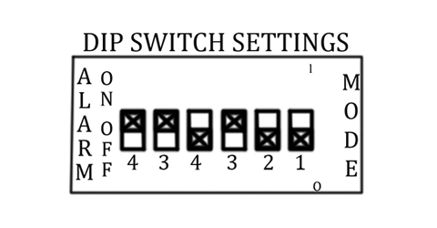
The below diagram shows the correct setting of the DIP Switches if using the relay in Direct Mode, which would be a pump down application. 
Note that Channels 1 and 2, which are the pump channels, are in the Down position, for Direct Mode. Pump down applications require the DIP Switches to be in Direct Mode. See below.
 Channels 3 and 4 are alarm channels, they are only single level service so they cannot be used for pump or valve control. Typically, one is used for high level, and the other is used for low level. In this situation Channel 3 will be low level, which is Inverse Mode, and Channel 4 will be high level, which is Direct Mode. See below.

The two additional DIP Switches all the way to the left, also labeled ‘3’ and ‘4’, control the load contacts located near the power supply contacts. See below.

Below show the load contacts that are controlled by these DIP Switches.
They control whether Channel 3, or Channel 4, or both are tied to these load contacts. For example, in this case, since both DIP Switches are Up (On Position), the ‘CH 3/4 Alarm’ load contacts will actuate if either Channel 3 or Channel 4 actuate. This will indicate that an alarm condition has occurred.
For further instructions please review the Series 67 Instruction Bulletin.
 SEARCH OUR RESOURCE CENTER
