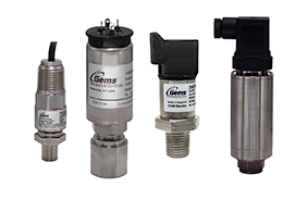
Many Gems sensor products offer a linear 4-20 milliamp (mA) output signal for transmitting to a receiver (meter/display, PLC, etc.) when measuring level or pressure. It is good to know the basics when troubleshooting or when choosing the best output signal for your application.
The most commonly used output for transmitting a linear signal is the two-wire 4-20 mA output. Its popularity is due to several beneficial properties. Using the current loop is a good option for long distance transmission. First, the accuracy of the signal is not affected by interconnected wiring over long distances with different conductors. Next, it allows for transmitting to several receivers wired in series in the loop as long as there is sufficient voltage supply to power all the devices (while not exceeding transmitter maximum voltage rating). Also, current loops make troubleshooting easier because you know that the input current you are reading at your PLC or display meter is the same value that is coming from your sensor or transmitter.
Another troubleshooting bonus when using the 4-20 mA current loop is the zero offset being at 4 mA instead of at 0 mA. Having the “zero-signal” actually be at 4 mA helps to more easily recognize failures due to a sensor lead break or open device. For instance, with a 0-20 mA current loop, there would be no immediate way to know if your 0mA signal was an actual zero-signal output or a broken wire.
Current loops are less sensitive to electrical noise than voltage transmission, and because it can transmit using very small DC voltages, it is also less likely to induce electrical noise emission to other conductors or equipment.
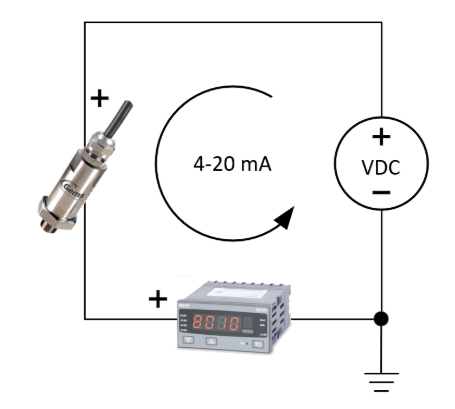
A 4-20 mA two-wire current loop in its most basic configuration consists of 4 components:

- Power supply
- Transmitter (or sensor)
- Receiver (meter, PLC, etc.)
- Conductor (wire)
Some things to note concerning the components of a 4-20 mA two-wire current loop; It use DC power, and the current source comes from the power supply (not the transmitter or sensor). The level of DC voltage supplied must be enough to drive all components in the loop while staying within their individual min/max voltage ranges. The transmitter/sensor translates the real-world condition (e.g. level, temperature, pressure) into the 4-20mA signal used by the receiver. The receiver scales the process variable range to match the 4-20 input providing a minimum and maximum value. You should also pay attention to the wire resistance and total impedance of the loop, especially in long distance applications.
Gems products using the two-wire 4-20mA current loop:
- XT Series Continuous Float Level Transmitters
- Pressure Transducers
- UCL Series Ultrasonic Continuous Level Transmitters
- SureSite Visual Liquid Level Indicators (Transmitter/Signal Conditioner optional)
- RLI-G Guided Wave Radar Level Sensor
- See Gems’ 4-20mA calibration instruction video HERE
- SureSite Transmitters & Signal Conditioners Wiring Guide HERE
 SEARCH OUR RESOURCE CENTER

